
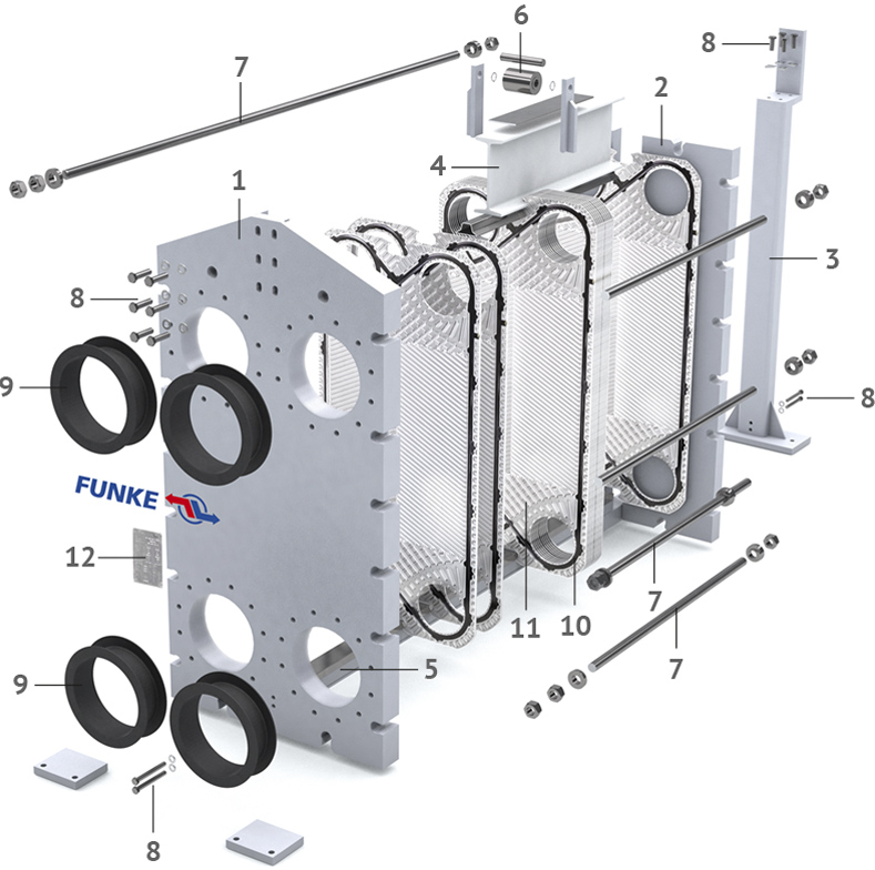
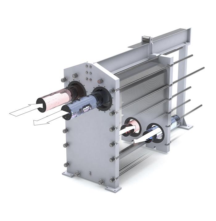
Gasketed plate heat exchangers consist of a set of adjoining embossed plates with apertures.
The plates are assembled at a 180° angle to each other, resulting in a flow gap. The gasket, which is mechanically secured or glued onto every plate, ensures that the flow gaps are securely sealed to the outside and from the second medium involved in the heat exchange.
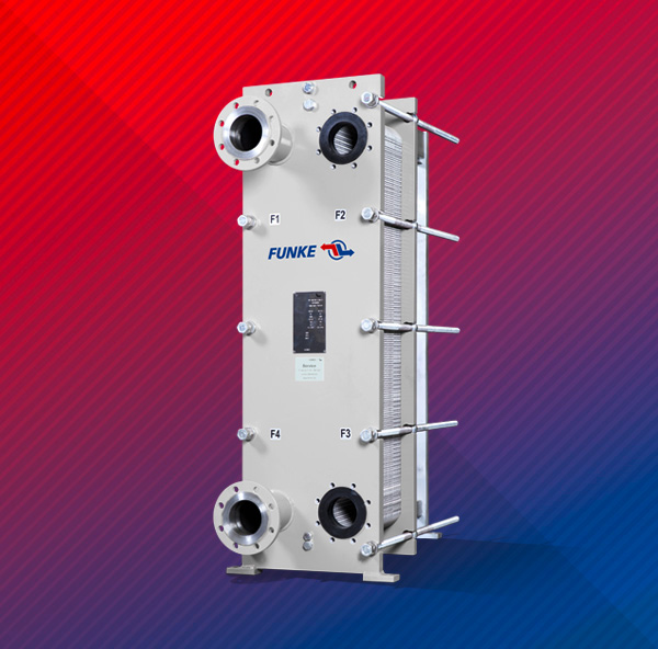
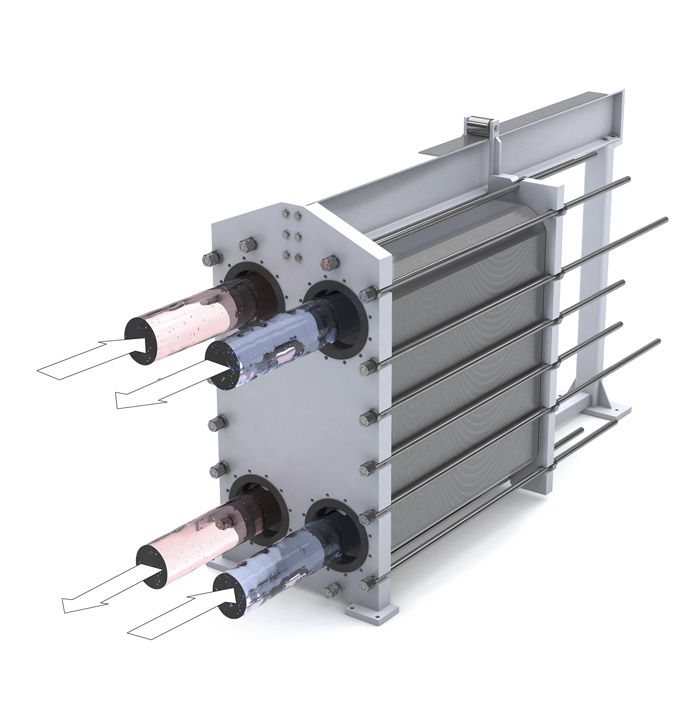
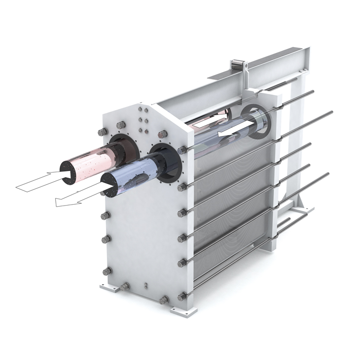
The plate assembly is mounted in a frame and compressed with tightening bolts between the fixed plate and the movable plate.
The gaskets of a plate heat exchanger experience a normal fatigue process over the course of their service life. Depending on the conditions of use, the plate assembly can be re-tightened several times until the lower limit is reached.
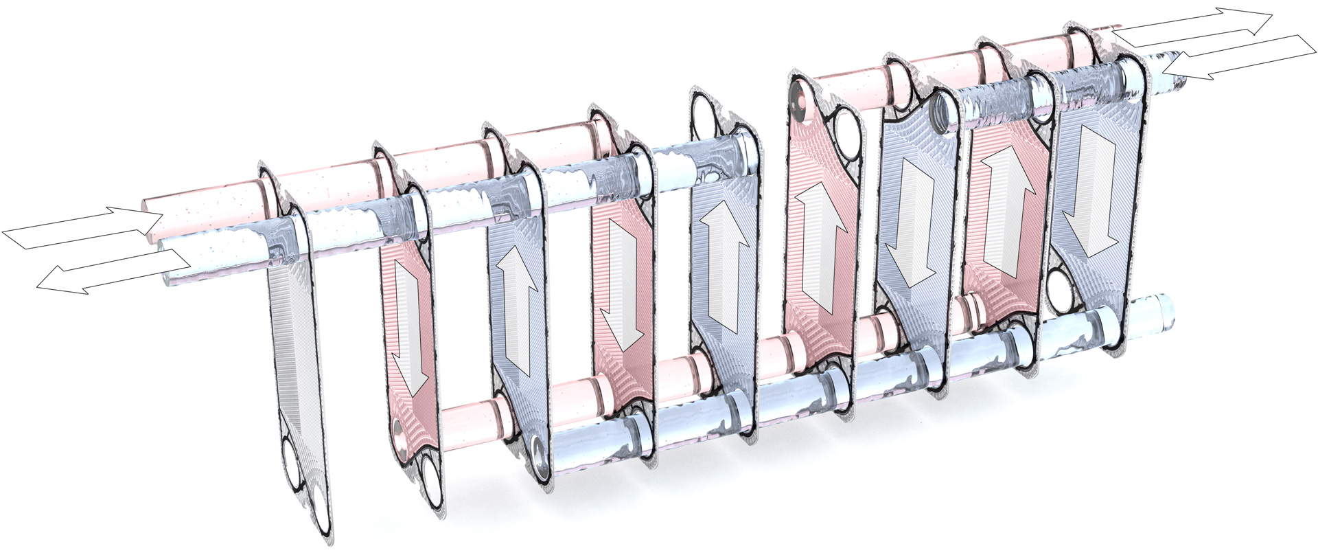
The connections of the media involved in the heat exchange are on the fixed plate, but can also be on the movable plate for multiple-pass flows. (see “Flow diagram”).
Our product range includes single and multiple-pass plate heat exchangers with heat exchange surfaces of up to 2,000 m².
Technical data |
|||
|---|---|---|---|
| Heat exchange surface per plate: | 0.04 - 3 m² | ||
| Max. operating pressure: | 25 bar | ||
| Max. operating temperature: | 200°C |
Our plates come with a double gasket at the inlet and outlet to prevent mixing of the two media. If designed as a safety heat exchanger, double plates are provided with a special gasket system.
FUNKE heat transfer plates are known for their thermodynamically and hydraulically optimized embossing, resulting in compact and cost-effective solutions.
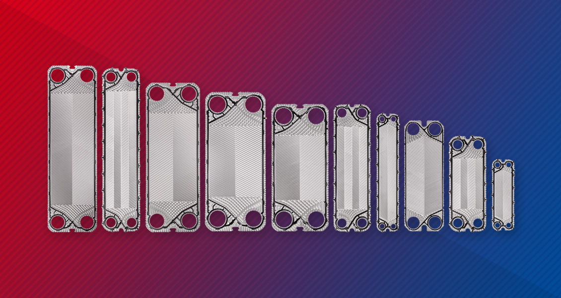
Depending on the application different plate materials are being used:
| HVAC | Industry | Power Plants | Chemistry/Petro-Chemistry | Renewable EnergiesTechnology |
|---|---|---|---|---|
| District heating/cooling | Hydraulics | Central cooling | Rafineries and processing (PE, PP etc.) |
Geothermal plants |
| Thermal power stations | Automotive industry | Lubricating oil cooler | Basic chemistry Acids, alkalines etc.) |
Solar power plants |
| Heating, ventilation, air conditioning | Process Technology (thermal plants, plastics etc.) |
Generator cooling | Special chemistry (Adhesives, coatings etc.) |
Water power plants |
| Swimming pool technology | Surface treatment | Auxiliary system cooling | Fine chemistry | Bioenergy |
| Supply technology | Compressor systems | Pharmaceutical industry | Wind power plants | |
| Food industry | Fuel cell technology |
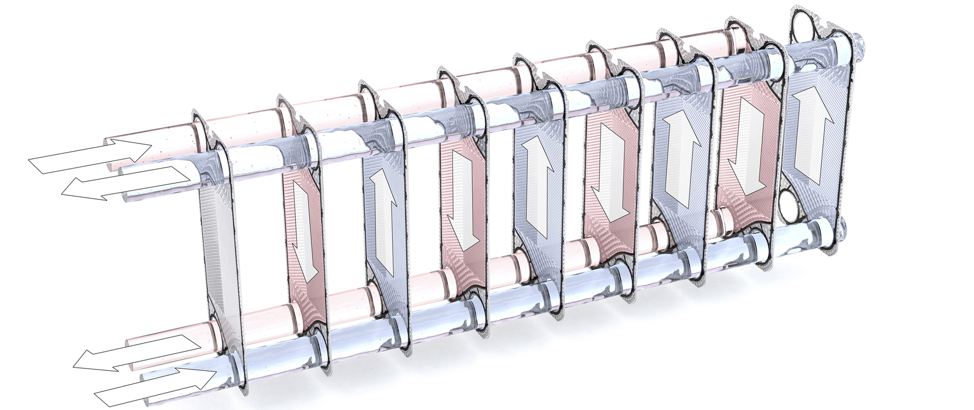
 single-pass
 Two-pass
 Three-pass